. QST . al XR-.IO) Stößel55^ Umdrehungen vom Massende.1.2, I^ – Slug-tuned (CTC LS-3 5-Mc. Spule).L3 – Slug-tuned (CTC LS-3 10-Mc. Spule). Slug- L5 – 25 Umdrehungen Nr. 26 cnam. Auf %-Zoll. diar-Tuned Form (CLC LS-.3). Die erforderliche Induktivität hängt von der Kapazität des Streukreises und der Länge des Koaxialkabels ab.s.b. Exciter.Si - Drehschalter, 1-polig, 3 Positionen, nicht verwendete Kontakte kurzgeschlossen (Centralab PA-18 mit PA-300 Index. Verwenden Sie alle Distanzstücke, die für die Montage des Abschnitts in der Nähe der Indexrückseite vorgesehen sind).Hinweis: Die 2.5-mh. Choke in der Oszillatorkathode CIR-Cu
1282 x 1949 px | 21,7 x 33 cm | 8,5 x 13 inches | 150dpi
Weitere Informationen:
Dieses Bild kann kleinere Mängel aufweisen, da es sich um ein historisches Bild oder ein Reportagebild handel
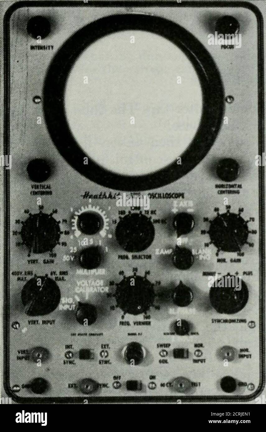
. QST . al XR-.iO) tapped55^ turns from ground end.1.2, I^ — Slug-tuned (CTC LS-3 5-Mc. coil).L3 —Slug-tuned (CTC LS-3 10-Mc. coil). slug- L5 — 25 turns No. 26 cnam. on %-inch. diar tuned form (ClC LS-.3).Note: See text for data on resonating slug-tuned coilsto proper frequencies. Inductance required depends onstray circuit capacitance and length of coax cable tos.s.b. exciter.Si — Rotary switch, 1 pole, 3 positions, unused contacts shorted (Centralab PA-18 with PA-300 index. Use all spacers furnished to mount section near rear of index).Note: The 2.5-mh. choke in the oscillator cathode cir-cuit should be of the small type such as National R-33. 12 QST for Versatilize Your Oscilloscope Adding a Z-Axis Amplifier and Voltage CalibratorBY LYLE E. SHARPE, * W6FSC THE addition of a Z-axis amplifier and voltagecalibrator to any scope provides a usefulasset and is not a difficult job. The oscillo-scope pictured in this article is a Heathkit model0-7, but thf^ Pfimp tofhniquo may be applied to. • This article describes the circuitry andconstruction involved in adding a Z-axisamplifier and voltage calibrator to anyoscilloscope lacking these refinements.The Z-axis amplifier may be used fortrace brightening, Z-axis modulation, or retrace blanking and. Mith the voltagecalibrator, the measurement of any wave-shape on the screen is available at theflick of a switch. Frout-puiicl itw of the scope with the additionalcontrols. *% Engineering Dept., J. B. Rea Co., Santa Monica, Calif. MULTIVIBRATOR any scope, providing necessary space for mount-ing the parts can be found. In this case, very littlespace was available immediately behind the frontpanel, so two small subchassis were fabricatedand set back on the main chassis with extensionshafts run through panel bushings for the controlknobs. As shown in the front-view photograph, the added rows of controls are placed midwaybetween the existing controls with the voltagecalibrator on the left side, and the Z-axis am-plifier on the